Extending a Traditional VIP to Solve PHY Verification Challenges
A comprehensive PHY verification plan must verify all of the PHY functionality in various conditions. Verification IP needs to serve hundreds of configurations and may not fit well for comprehensive PHY verification. A PCI Express Verification IP in itself covers more than 500 configurations. This creates the need of an extended version of Verification IP which completely focus on PHY related aspects.

-
Introduction
The common PHY found in PCI Express, USB 3.0 and 3.1, and SATA devices help accelerate development of these devices by implementing the physical layer functionality as a discrete IC or macro cell, which can easily be included in ASIC designs. In bus-based layered protocols, PHY typically provides the following functionality:
- Various serial data transmission rates
- 8, 16, or 32-bit parallel interface to transmit and receive data
- Recovery of data and clock from the serial stream
- Holding registers to stage transmit and receive data
- Direct disparity control to transmit compliance patterns
- Various encode/decode and error indications
- Receiver detection
- Beacon transmission and reception
- Low Frequency Periodic Signaling (LFPS) transmission
- Selectable Tx margining, Tx de-emphasis, and signal swing values
- COMINIT and COMRESET transmission and reception
- Multi-lane de-skew
In this paper, the PHY features are described in the context of PCI Express and USB protocols. However, in terms of the PHY verification methodology, this paper applies to all serial protocols that use a common PHY.
PHY Verification Environment
Usually, a PHY verification environment requires one bus functional model (BFM) at the serial interface and another at the PIPE interface. In Figure 1, the VIP acts as the USB host or the PCIe RC at the PIPE interface and as the USB device or the PCIe EP at the serial interface. However, in Figure 2, the connections are flipped.
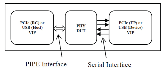
Figure 1: VIP as USB Host or PCIe RC
-
Download Paper
-