A Guide to UPF-based Power Intent Verification with Questa One
This white paper takes a close look at the verification side of UPF with Questa One Sim Power Aware. The focus here is on how to confirm that the described power intent is correctly wired up, tested and functionally sound throughout the design flow. We’ll look at multiple verification approaches and review the tools and technologies offered by Questa One that help design teams close the loop on low-power verification.

-
Introduction
The race for more energy-efficient and battery-powered electronics has fundamentally reshaped the way digital systems are designed. From smartphones to wearables to edge AI, managing power is no longer just an afterthought – it’s a core design constraint that impacts everything from performance and thermal budget to cost and product longevity. Teams that fail to integrate power intent early often face late-stage surprises, costly rework and missed tape outs. To address this, the industry has standardized around IEEE 1801 Unified Power Format (UPF), enabling teams to define, verify and reuse power intent independent of functional RTL.
But introducing UPF into the design flow brings its own set of challenges. Just having a UPF file in place – with power domains, isolation controls and retention logic defined – doesn’t automatically ensure that the design behaves correctly in all operating conditions. If that power intent isn’t thoroughly verified, subtle bugs can slip through, leading to issues like silent data corruption, functional breakdowns or inefficient power usage that only surface late in the cycle.
This white paper takes a close look at the verification side of UPF with Questa™ One Sim Power Aware. The focus here is on how to confirm that the described power intent is correctly wired up, tested and functionally sound throughout the design flow. We’ll look at multiple verification approaches and review the tools and technologies offered by Questa One that help design teams close the loop on low-power verification.
Understanding Power Intent in UPF
The UPF, formalized as IEEE 1801, was developed to give engineers a way to describe how power is managed in a chip without having to embed that information directly into the RTL. By separating RTL from power intent, the design can be reused and can target multiple market segments. Instead of mixing functional logic with power control, UPF provides a clean way to define things like how and when parts of the design can be shut down or what needs to be preserved during a power-off event.
Central to UPF is the concept of power domains. These are groups of modules that share the same power supply and can be turned on or off independently. To keep signals from behaving unpredictably when parts of the chip are powered down, isolation cells are used at the boundaries between domains. Similarly, retention registers are employed to hold critical data during shutdown so that the system can pick up where it left off when power is restored. Level shifters also play a key role, handling voltage transitions when signals move between domains running at different supply levels.
Getting this right is important. If, for example, isolation logic is missing or retention controls aren’t correctly configured, the result could be anything from random glitches to complete functional failure – and these issues often won’t show up in a standard simulation. That’s why a solid power-aware verification plan is essential. It ensures that the power intent described in UPF is implemented as expected and that the system will behave reliably under all power conditions.
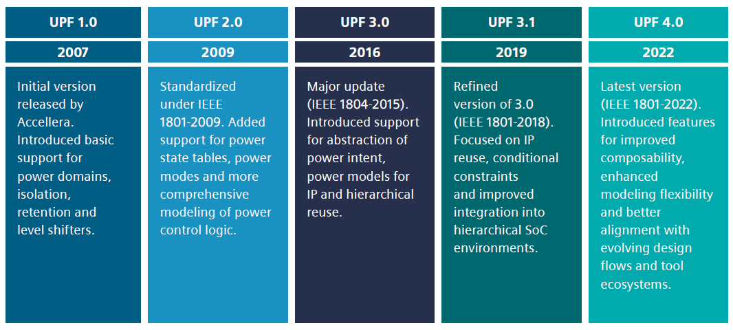
Figure 1. The evolution of UPF.
-
Download Paper