I am trying to create a simple model of my UVM testbench to test out some functionality I would like to add for wires. My simple interface looks like this:
interface int_1(input logic clk);

  logic [3:0] x;
  logic [13:7] y; // 6 bits
  logic w;
  wire z;

  // Some other tasks to drive x, y, w

  task set_z_one();
    z = 1'b1;
  endtask

  task set_z_zero();
    z = 1'b0;
  endtask

  task z_wiggle();
    z = 1'b0;
    @(posedge clk);
    z = 1'b1;
    @(posedge clk);
  endtask
However I am getting this error:
Error-[IBLHS-NT] Illegal behavioral left hand side
basic/int_1.sv, 90
  Net type cannot be used on the left side of this assignment.
  The offending expression is : z
  Source info: z = 1'b1;
But I am driving wires in my UVM drivers just fine with almost the same syntax! Can someone please explain to me what I am doing wrong? I can’t replace the wire type with logic because the point of the simple model is specifically to test a new functionality out for wires.
For comparison, this code is my big UVM testbench works fine: (Changed variable and other names for clarity, please ignore small spelling errors)
IFC:
In order for a net to be driven via a virtual interface, the interface itself must provide a procedural means to do so. This can be accomplished either via a clocking block or by including a driver that is updated by a continuous assignment from a variable within the interface.
Your example driver code doesn’t use your clocking block, but are you in fact actually using it? That makes all the difference.
In reply to warnerrs:
Below is a link to a simple model that demonstrates that a wire (data) in an interface can be drivern by a task in a class.
I totally agree. OP’s example driver class is directly driving the wire from a class, not going through a clocking block, which I think is illegal, and is what I was pointing out. Some tools may allow that though.
I totally agree. OP’s example driver class is directly driving the wire from a class, not going through a clocking block, which I think is illegal, and is what I was pointing out. Some tools may allow that though.
I believe that driving a wire thru a task is illegal.
Quote:
1800-2012 14.3 Clocking block declaration
A clockvar whose clocking_direction is inout shall behave as if it were two clockvars, one input and one output, having the same name and the same clocking_signal.
Reading the value of such an inout clockvar shall be equivalent to reading the corresponding input clockvar.
Writing to such an inout clockvar shall be equivalent to writing to the corresponding output clockvar.
Here is a simple model:
module top;
  timeunit 1ns;     timeprecision 100ps;
    bit clk, a, b;
    wire w;

    initial forever #10 clk=!clk;
    task t();
        w = 1'b1;  // ILLEGA !!!!
    endtask

    initial begin
        #10;
        t();
        $stop;
    end
endmodule
On EDA Playground
I gat “w is not a valid left-hand side of a procedural assignment.”
I also get an illegal message on other tools.
Thus, to drive a wire thru a task, you got to go thru a clocking block and modport and variable clocking_direction as inout
Thanks so much for your answers! I have added clocking blocks and that solves the problem.
For the big_driver/ big_ifc example, the variable x is not driven through a clocking block. However, I omitted the run phase which has a case statement to call the different tasks based on the command in the transaction.
    virtual task run_phase(uvm_phase phase);
        forever begin
            // Grab the next sequence item to process
            `uvm_info(tID, "Waiting for next item to process", UVM_DEBUG)
            seq_item_port.get_next_item(req);
            $cast(rsp, req.clone());
            rsp.set_id_info(req);
            id = rsp.get_transaction_id();

            `uvm_info(tID, $sformatf("Trans (%0d): Starting\n%s", id, rsp.sprint()), UVM_DEBUG)

            // Record the transaction
            void'(begin_tr(rsp));

            // Now call the correct task/function based on the command
            case (req.command)
                big_command::DEFAULT_INPUTS : setDefaultInputs();              // Set the default input values for our pins
                big_command::SET_ALL_X_HIGH : set_all_x_high();
                default        : `uvm_error(tID, $sformatf("Trans (%0d) : Currently don't know how to implement the request", id))
            endcase

            // Done with this transaction
            `uvm_info(tID, $sformatf("Trans (%0d) : Finished with transaction", id), UVM_DEBUG)
            end_tr(rsp);
            seq_item_port.item_done();
        end
    endtask : run_phase
Does this count as a “procedural means to drive a net through a virtual interface”? The small example and the big testbench have the same simulator, so there must be something in my omitted code that causes the difference.
Regardless, my problem is solved. Thanks for the help!
I was in the SVA 1800 committee, but not in the main sv language committee.
It is odd that you can put a value on a wire thru a procedural block (task) using a clocking block. 1800 says “Writing to such an inout clockvar shall be equivalent to writing to the corresponding output clockvar”. Looks to me that this is bypass way to remove the restriction that a wire cannot be driven by a procedural block.
Would like to hear about this topic from someone in the language committee who can clarify how this came about.
Ben systemverilog.us
It is illegal to make procedural assignments to wires. When you declare clocking block outputs, you are declaring another signal associated with the wire or variable of the same name. You use a clocking block drive statement to schedule an assignment to a clocking block output variable, which then gets assigned to the original signal.
In reply to ben@SystemVerilog.us:
It is illegal to make procedural assignments to wires. When you declare clocking block outputs, you are declaring another signal associated with the wire or variable of the same name. You use a clocking block drive statement to schedule an assignment to a clocking block output variable, which then gets assigned to the original signal.
Thanks Dave! I see the following equivalence for “data” from what you are describing
:
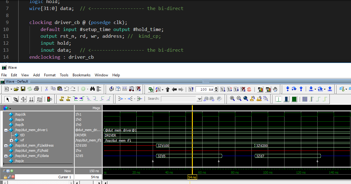
 clocking driver_cb @ (posedge clk);
		default input #setup_time output #hold_time;
		output rst_n, rd, wr, address; //  kind_cp;
		input hold;
		inout data;   // <------------------- the bi-direct
	endclocking : driver_cb
wire[31:0] data;  // <------------------- the bi-direct
Logic[31:0] data_var;  // <------------------- the cb temp

always_comb #hold_time data=data_var:
// nonblocking assignment to data is equivalent to a nonblocking assessment to data_var, and
// then data_var gets assigned to data after a hold time, as defined in the clocking block.
Questions: in what version (year) of 1800 did the clocking block came about? Also, was this the result of uvm?
Thanks, Ben systemverilog.us
Questions: in what version (year) of 1800 did the clocking block came about? Also, was this the result of uvm?
Clocking blocks were introduced by the 2002 Vera language donation to SystemVerilog 3.1. In Vera, you do not communicate directly with Verilog signals. It set up a PLI sampling and driving mechanism, and the clocking block was intended to replace that. This was all long before there was an AVM/OVM/UVM.