It would be helpful to provide a written description of your requirements using words to compare them with the timing diagram and code.
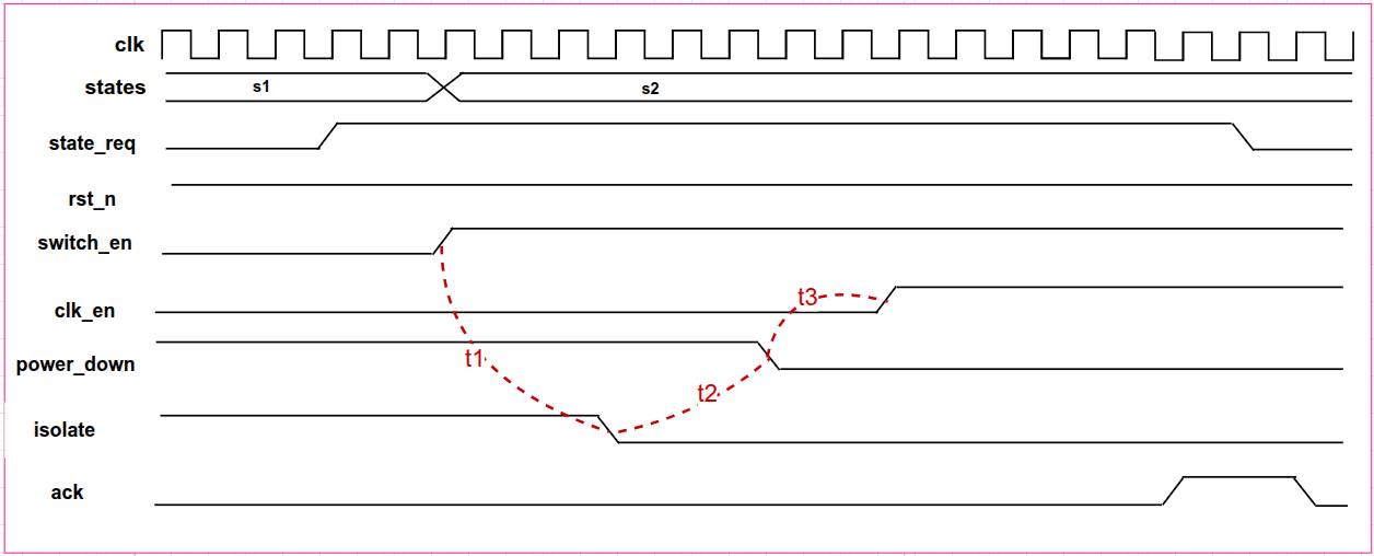
Your assertion says $rose(state_req) and $rose(switch_en) overlapping the same clock cycle, but the timing diagram shows them two clock cycles apart. Also the delay between $rose(clk_en) and $rose(ack) and the delay between $rose(ack)and$fell(state_req)` is the same in the assertion and different in the timing diagram.
It should be straightforward to create a test bench for the passing version of the assertion, along with several test cases that will make it fail.
Thanks @dave_59
In state s2, switch_en for switching different power domains so it doesn’t matter clk_cycles between state_req and switch_en.
Irrispective of clock cycles, the requirement is whenever fsm state request to move from s1 to s2 state then state_req becomes high and it moves to s2 and reset becomes active low reset=1, after changing state s2 the switch_en=1 after t1 period isolate goes low and after t2 period power_down goes low aftert2 period clk_en=1 then after some delay ack goes high follwed by state_req goes low followed by ack goes low.
This partricular timing behaviour need to check with assertion.
Finally, without referring my assertion can you try with timing diagram and later I’ll compare.
can you write Assertion somewhat there in the waveform. $rose(state_req) and $rose(switch_en) : 2 cycles before switch_en state_req becomes high.
and when clk_en is high after some random delay ack goes high followed by state_req goes low followed by ack goes low.