VERIFICATION ASYNCHRONOUS FIFO CUMMINGS

I am completely new to the SystemVerilog world, and I am trying to verify the asynchronous FIFO made by Cummings.

The goal is to verify this design by using the Tb components, so no UVM at all. I should basically focus on Generator (or sequencer), Driver, Interface, Monitor and Scoreboard.

There are at least 5 situations that I would like to verify which are: read only, write only, read/write at the same time, write when the FIFO is full, and read when the FIFO is empty.

Is it better to use two agents by splitting the write side and read side? If so, how can I realise the communication between the two of them when they need to provide the inputs and outputs to the monitor? Or is it better to use only one agent?

My original idea was to use a transaction with some constraints where I could use a 2-bit mode which is randomized and according to its value, I would have provided a specific stimulus (if mode =2’b00, then {winc, rinc} =2’b00 etc.) so that the Generator could just randomize all the inputs and eventually I should have at least 3 cases covered (write only, read only and write/read at the same time).

For the Write Full and Read Empty: I know the depth of the FIFO, and I would just declare a task that repeats itself one more time after the entire FIFO is filled and etc.

The point of this question is: is there any better way to proceed? Am I going in the wrong way? Maybe it’s because I am unexperienced, but by randomizing everything and telling the generator to generate, don’t know, 100 transactions, eventually every case will be covered I guess. Is a solution like this wrong?

In reply to GiuseppeT:

I am completely new to the SystemVerilog world, and I am trying to verify the asynchronous FIFO made by Cummings.

In 2002 I wrote the book Real Chip Design and Verification Using Verilog and VHDL($3) https://rb.gy/cwy7nb That book includes Cumming async Fifo. It includes the following files:
bin2gray.v, gray2bin.v, graycntr.v, fifo_async.v, fifo_async_tb.v
If you need those files, let me know.

The goal is to verify this design by using the Tb components, so no UVM at all. I should basically focus on Generator (or sequencer), Driver, Interface, Monitor and Scoreboard.
There are at least 5 situations that I would like to verify which are: read only, write only, read/write at the same time, write when the FIFO is full, and read when the FIFO is empty.
Is it better to use two agents by splitting the write side and read side? If so, how can I realise the communication between the two of them when they need to provide the inputs and outputs to the monitor? Or is it better to use only one agent?

I would use one sequencer that based on the kind of transaction need would trigger the necessary task (e.g., read only, write only, delays, read & write, idle). The tasks will most likely include fork/join to execute the needed transactions and to store the write data into a queue. The interface should include assertions.

My original idea was to use a transaction with some constraints where I could use a 2-bit mode which is randomized and according to its value, I would have provided a specific stimulus (if mode =2’b00, then {winc, rinc} =2’b00 etc.) so that the Generator could just randomize all the inputs and eventually I should have at least 3 cases covered (write only, read only and write/read at the same time).
For the Write Full and Read Empty: I know the depth of the FIFO, and I would just declare a task that repeats itself one more time after the entire FIFO is filled and etc.

You have the right concepts. From my donated book A Pragmatic Approach to VMM Adoption
http://SystemVerilog.us/vf/VMM/VMM_pdf_release070506.zip
http://SystemVerilog.us/vf/VMM/VMM_code_release_071806.tar


class Fifo_xactn extends vmm_data; 
 import fifo_pkg::*; 
 rand fifo_scen_e kind; 
 rand word_t data; // in : data to push 
 rand int idle_cycles; 
 time xactn_time; 
 static vmm_log log = new("Fifo_xactn", //name 
 "class");6 // instance 
 constraint cst_idle { 
 idle_cycles inside {[1:3]}; 
 } 
 constraint cst_xact_kind { 
 kind dist { 
 PUSH := 400, 
 POP := 300, 
 PUSH_POP :=200, 
 IDLE := 300, 
 RESET := 1 
 }; 
 } // cst_xact_kind 
…
Figure 2.2.2.1-1 

The point of this question is: is there any better way to proceed? Am I going in the wrong way? Maybe it’s because I am unexperienced, but by randomizing everything and telling the generator to generate, don’t know, 100 transactions, eventually every case will be covered I guess. Is a solution like this wrong?

I would use assertions in the interface to do the verification. The interface would include the queue for the storage of data. You can also write cover property statements to make sure that you covered the needed sequences.

Ben Cohen
http://www.systemverilog.us/ ben@systemverilog.us
** SVA Handbook 4th Edition, 2016 ISBN 978-1518681448

  1. SVA Package: Dynamic and range delays and repeats SVA: Package for dynamic and range delays and repeats - SystemVerilog - Verification Academy
  2. Free books:
  1. Papers:
    Understanding the SVA Engine,
    https://verificationacademy.com/verification-horizons/july-2020-volume-16-issue-2
    Reflections on Users’ Experiences with SVA, part 1
    Reflections on Users’ Experiences with SVA
    Reflections on Users’ Experiences with SVA, part 2
    Reflections on Users’ Experiences with SVA, Part II
    Understanding and Using Immediate Assertions
    Understanding and Using Immediate Assertions
    SUPPORT LOGIC AND THE ALWAYS PROPERTY
    http://systemverilog.us/vf/support_logic_always.pdf
    SVA Alternative for Complex Assertions
    https://verificationacademy.com/news/verification-horizons-march-2018-issue
    SVA in a UVM Class-based Environment
    https://verificationacademy.com/verification-horizons/february-2013-volume-9-issue-1/SVA-in-a-UVM-Class-based-Environment
    SVA for statistical analysis of a weighted work-conserving prioritized round-robin arbiter.
    https://verificationacademy.com/forums/coverage/sva-statistical-analysis-weighted-work-conserving-prioritized-round-robin-arbiter.
    Udemy courses by Srinivasan Venkataramanan (http://cvcblr.com/home.html)
    https://www.udemy.com/course/sva-basic/
    https://www.udemy.com/course/sv-pre-uvm/

In reply to ben@SystemVerilog.us:

My supervisor told me to not use Assertions so for the moment, don’t want to lie but I don’t even know what they are. He told me to just focus on those 5 situations that I need to verify and to do that, I was trying to realize 2 agents which, if I understood correctly, means to realize one sequencer (or generator), one driver and one monitor for each agent.

The two agents then should share a common Scoreboard to check the results and apply the operations; that at least is the idea that I am currently following.

Point is, I kinda feel insecure about the SystemVerilog code that I am writing since I have no one to check on it and literally I have finished a SV course without absorbing concepts yet.

About using the Queue, I thought about using this in the Reference Model, the one which gets the inputs from the Stimulus Monitor, to recreate the behaviour of the design somehow; I should basically recreate those 5 situations mentioned early in the Sequencer/Driver, like creating some tasks I guess? Sorry, I know what to do but maybe I cannot translate it in SV syntax

In reply to GiuseppeT:

In reply to ben@SystemVerilog.us:
My supervisor told me to not use Assertions so for the moment, don’t want to lie but I don’t even know what they are. He told me to just focus on those 5 situations that I need to verify and to do that, I was trying to realize 2 agents which, if I understood correctly, means to realize one sequencer (or generator), one driver and one monitor for each agent.

[Ben] You can specify the kind of situation to test thru the use of a variable of enum type
and then based on the value of the variable fire concurrent tasks using the fork-join construct. for example, (conceptual code


// Updated from the link of my VMM model 
package fifo_pkg;
  timeunit 1ns; timeprecision 100ps;
  `define TOP fifo_tb
  // My update for the situation
  //  read only, write only, read/write at the same time, 
  //  write when the FIFO is full, and read when the FIFO is empty.
  typedef enum {RD, WR, RD_WR, WR_FULL, RD_MT} situation_e;

  typedef enum {PUSH, POP, PUSH_POP, IDLE, RESET} fifo_scen_e;
  typedef enum {PUSH_MODE, POP_MODE} mode_e;
  typedef enum {PASSED, FAILED} fifo_status_e;
  typedef enum {DONE_GEN, DONE_BFM} notification_e;
  parameter BIT_DEPTH = 4;
  parameter FULL = 16;    
  parameter WIDTH = 32;
  typedef   logic [WIDTH-1 : 0] word_t;
  typedef   logic[31:0] wword_t;
  typedef   logic [WIDTH-1 : 0] wire_word_t;
  typedef   word_t [0 : (2**BIT_DEPTH-1)] buffer_t;

  parameter 		 ALM_EMPTY_REG = 2'b00;
  parameter 		 ALM_FULL_REG = 2'b01;

endpackage : fifo_pkg

The two agents then should share a common Scoreboard to check the results and apply the operations; that at least is the idea that I am currently following.

Again, I would use one agent because it is much simpler. For example,


// package alsready imported 
task Fifo_cmd_xactor::main();
    Fifo_xactn  fifo_xactn_0;  // transaction to get 
    Fifo_response  fifo_response; // response to generator
    // typedef enum {RD, WR, RD_WR, WR_FULL, RD_MT} situation_e;
    situation_e situation; 
      fifo_xactn_0 =new(); 
    // DIrected tests with some randomness depending upon the situation 
    // Do  5 reads
    situation=RD; 
    bit[0:2] delay; 
// READ 
    randomize(delay);
    repeat(5) @(posedge rd_clk) 
       fork rd_task(delay); 
       join // joins at end of task processing 
    randomize(delay);
// WRITE
    repeat(4) @(posedge wr_clk) 
       fork wr_task(delay); 
       join // joins at end of task processing 
... 
// If you want to mix those five situations: 
// RD, WR, RD_WR, WR_FULL, RD_MT
     if (!randomize(situation) with {
        situation dist {RD:=1, WR:=2, RD_WR:=1, WR_FULL:=0, RD_MT:=0};
      }) $error(" randomization failed"); 
 
      case (situation)
        RD: this.rd_task(dealy); 
        WR  : ...  
      endcase 
  endtask : main
// THose task calls above are calls to the driver and to the monitor.


Point is, I kinda feel insecure about the SystemVerilog code that I am writing since I have no one to check on it and literally I have finished a SV course without absorbing concepts yet.
About using the Queue, I thought about using this in the Reference Model, the one which gets the inputs from the Stimulus Monitor, to recreate the behaviour of the design somehow; I should basically recreate those 5 situations mentioned early in the Sequencer/Driver, like creating some tasks I guess? Sorry, I know what to do but maybe I cannot translate it in SV syntax

10 years ago I wrote a UVM model for a counter. I didn’t touch it since.
I am giving you this model in the hope that it might guide you in modeling what you need.
You can commentt out all those UVM includes and simplify the model.
http://systemverilog.us/vf/uvm_counter.zip

Best of luck,
Ben

In reply to ben@SystemVerilog.us:

Mmh first of all, thank you so much for your patience with me. Really appreciating the fact that you’re doing everything that you can to lead me in the right direction.

By taking a look at your code example, I get why you’re suggesting me to use only one agent, because maybe in the Generator file I can randomize situation variable which is a typedef enum type and according to its value, I can do something in the case statement; like, if situation is == RD, then I am going to provide to the Driver Read_enable ==1, Write_enable==0 etc and basically I can do this for each case (correct me if I am wrong).

My problem with one Agent would be: how can I deal with the two asynchronous clocks in the interface, driver and monitor? Driver and Monitor work for sure with a clock signal, so how am I supposed to know which one to use? In my case, the Write_clock is faster than the read_clock, I cannot use the write_clock signal to drive the read signals to the interface from the Driver…does it make sense for you what I am trying to say? Hope it does

Thanks for the model for the counter, going to check it right now.

In reply to GiuseppeT:

In reply to ben@SystemVerilog.us:
Mmh first of all, thank you so much for your patience with me. Really appreciating the fact that you’re doing everything that you can to lead me in the right direction.
By taking a look at your code example, I get why you’re suggesting me to use only one agent, because maybe in the Generator file I can randomize situation variable which is a typedef enum type and according to its value, I can do something in the case statement; like, if situation is == RD, then I am going to provide to the Driver Read_enable ==1, Write_enable==0 etc and basically I can do this for each case (correct me if I am wrong).

[Ben] You’re correct. In fact, the whole verification can be done in one module with no classes, but tasks would be helpful. But you have an assignment.

My problem with one Agent would be: how can I deal with the two asynchronous clocks in the interface, driver and monitor? Driver and Monitor work for sure with a clock signal, so how am I supposed to know which one to use? In my case, the Write_clock is faster than the read_clock, I cannot use the write_clock signal to drive the read signals to the interface from the Driver…does it make sense for you what I am trying to say? Hope it does

I understand your concern, but they are overdriven (exaggerated).
I am including a model from my SVA 4th edition assertion book. This model checks thru assertions a FIFO-like model where data is written at one rate(33MHz) into a black box is read at a slower rate(25MHz).

  1. I emulated my FIFO black box with a queue
    int dataQ [$]; // queue, to store/read incoming data
  2. On Writes, I push front, syncked to the wr33 clk
    if (wr_33) dataQ.push_front(wdata); // store data
  3. On Reads, I pop from the back
    rdata_from_q <= dataQ.pop_back();
  4. To check that the data read is correct, I wrote this assertion

// Data integrity check
property p_read_data_integrity;
@(posedge clk_rcv25)
rd_25 |=>  rdata_from_q==rdata;
endproperty : p_read_data_integrity
ap_read_data_integrity : assert property (p_read_data_integrity);
// Assertion is equivalent to
// Updated 1/27/2023  See my paper rb.gy/mu4ttk
//
always @(posedge clk_rcv25)
if(rd_25) fork
do_check();
join_none
task automatic do_check();
@(posedge clk_rcv25) assert(rdata_from_q==rdata);
// same as **if (!(rdata_from_q==rdata)) $error;**
// I used the automatic task to avoid missing errors for continuous reads

  1. As you can see, the monitor is the queue that can handle the writes and reads separately or concurrently. Study my model, and if you are serious about going into the design and verification field, take a close looks at my books (some free). I put a lot of efforts into them, and provided lots of real examples.
//   The data received from an interface (with wr control) must be properly 
//   transferred to the receiving hardware (with rd control).
//   The data is sourced at a 33 MHz rate and is extracted at a 25 MHz rate.
//   The receiver uses a ready4data signal to throttle the transmission
//   of one Kilo-words of data block.  The data extracted by the receiver
//   is in the same order that it was transmitted. 
module bus_xfr_data_integrity_check (
  input wr_33, // Transmitter write signal @33MHz
  input rd_25,  // Receiver   read signal @25 MHz
  input int wdata, // write data frofm Transmitter
  input int rdata, // read data from Receiver
  input reset_n, // active low reset
  input clk_xt33,   // clock transmitter @33 MHz
  input clk_rcv25); // clock Receiver @25 MHz
  timeunit 1ns;   timeprecision 100ps;

  parameter MAX_BUFF_SIZE=1024; 
//  int waddr;  // write address for storage of incoming data
//  int raddr;  // read address for reading of received data
  int rdata_from_q; // read data from queue to compare to Receiver
  int dataQ [$]; // queue, to store/read incoming data
  logic read_q_on_MT; // for waveform 
  
  logic[7:0] dataQ_size;
  assign dataQ_size  = dataQ.size; // dynamic arrays illegal in properties
  

  // Storage of data into queue
  always @ (posedge clk_xt33)
    if (reset_n==1'b0)
      dataQ 		 = {}; // clear the queue contents
    else begin
      if (wr_33) dataQ.push_front(wdata);  // store data
      end
  

  // Collect data from the Q 
  always @ (posedge clk_rcv25)
    if (rd_25 && dataQ_size!=0)  begin 
       rdata_from_q <= dataQ.pop_back();
	  read_q_on_MT 	<= 1'b0;
	  end 
     else begin 
       rdata_from_q <= 0;
	   read_q_on_MT <= 1'b1;
	 end     

  // Data integrity check 
  property p_read_data_integrity; 
    @(posedge clk_rcv25)
      rd_25 |=>  rdata_from_q==rdata;
  endproperty : p_read_data_integrity
  ap_read_data_integrity : assert property (p_read_data_integrity);

  // Never a READ with no data received
  property p_never_read_on_empty;
    @(posedge clk_rcv25)
      not (dataQ_size == 0 && rd_25);
  endproperty : p_never_read_on_empty
  ap_never_read_on_empty : assert property (p_never_read_on_empty);

  // never a write on a full buffer 
  property p_write_on_max_buff;
    @(posedge clk_xt33)
      not (dataQ_size == MAX_BUFF_SIZE && wr_33);
  endproperty : p_write_on_max_buff
  ap_write_on_max_buff : assert property (p_write_on_max_buff);


endmodule : bus_xfr_data_integrity_check
  
module top;
  timeunit 1ns;   timeprecision 100ps;
  logic wr_33=0; // Transmitter write signal @33MHz
  logic rd_25=0;  // Receiver   read signal @25 MHz
  int wdata; // write data from Transmitter
  int rdata; // read data from Receiver
  logic reset_n=1; // active low reset
  logic clk_xt33=1;   // clock transmitter @33 MHz
  logic clk_rcv25=1; // clock Receiver @25 MHz

  bus_xfr_data_integrity_check b_chk(.*);
  
  initial begin 
    reset_n =0;
	#100 reset_n =1;
  end  
  initial forever #30 clk_xt33=!clk_xt33;
  initial forever #40 clk_rcv25 =!clk_rcv25;
  always @ (posedge clk_xt33)
    assert(randomize(wr_33, wdata));
  always @ (posedge clk_rcv25)
    assert(randomize(rd_25, rdata));
endmodule : top   

Thanks for the model for the counter, going to check it right now.

++ 4 U

Ben Cohen
http://www.systemverilog.us/ ben@systemverilog.us
** SVA Handbook 4th Edition, 2016 ISBN 978-1518681448

  1. SVA Package: Dynamic and range delays and repeats SVA: Package for dynamic and range delays and repeats - SystemVerilog - Verification Academy
  2. Free books:
  1. Papers:
    Understanding the SVA Engine,
    https://verificationacademy.com/verification-horizons/july-2020-volume-16-issue-2
    Reflections on Users’ Experiences with SVA, part 1
    Reflections on Users’ Experiences with SVA
    Reflections on Users’ Experiences with SVA, part 2
    Reflections on Users’ Experiences with SVA, Part II
    Understanding and Using Immediate Assertions
    Understanding and Using Immediate Assertions
    SUPPORT LOGIC AND THE ALWAYS PROPERTY
    http://systemverilog.us/vf/support_logic_always.pdf
    SVA Alternative for Complex Assertions
    https://verificationacademy.com/news/verification-horizons-march-2018-issue
    SVA in a UVM Class-based Environment
    https://verificationacademy.com/verification-horizons/february-2013-volume-9-issue-1/SVA-in-a-UVM-Class-based-Environment
    SVA for statistical analysis of a weighted work-conserving prioritized round-robin arbiter.
    https://verificationacademy.com/forums/coverage/sva-statistical-analysis-weighted-work-conserving-prioritized-round-robin-arbiter.
    Udemy courses by Srinivasan Venkataramanan (http://cvcblr.com/home.html)
    https://www.udemy.com/course/sva-basic/
    https://www.udemy.com/course/sv-pre-uvm/

In reply to ben@SystemVerilog.us:
Made a correction; needed the fork -join_none


// Data integrity check 
  property p_read_data_integrity; 
    @(posedge clk_rcv25)
      rd_25 |=>  rdata_from_q==rdata;
  endproperty : p_read_data_integrity
  ap_read_data_integrity : assert property (p_read_data_integrity);
// Assertion is equivalent to 
// Updated 1/27/2023  See my paper rb.gy/mu4ttk
// 
always @(posedge clk_rcv25) 
   if(rd_25) fork 
               do_check();
             join_none
task automatic do_check(); 
   @(posedge clk_rcv25) assert(rdata_from_q==rdata);
 

In reply to ben@SystemVerilog.us:

Thank you for the FIFO model you provided me, it is really clear and, despite not knowing that much of assertions because my supervisor told me to not use them, I believe I understood what the entire code is doing.

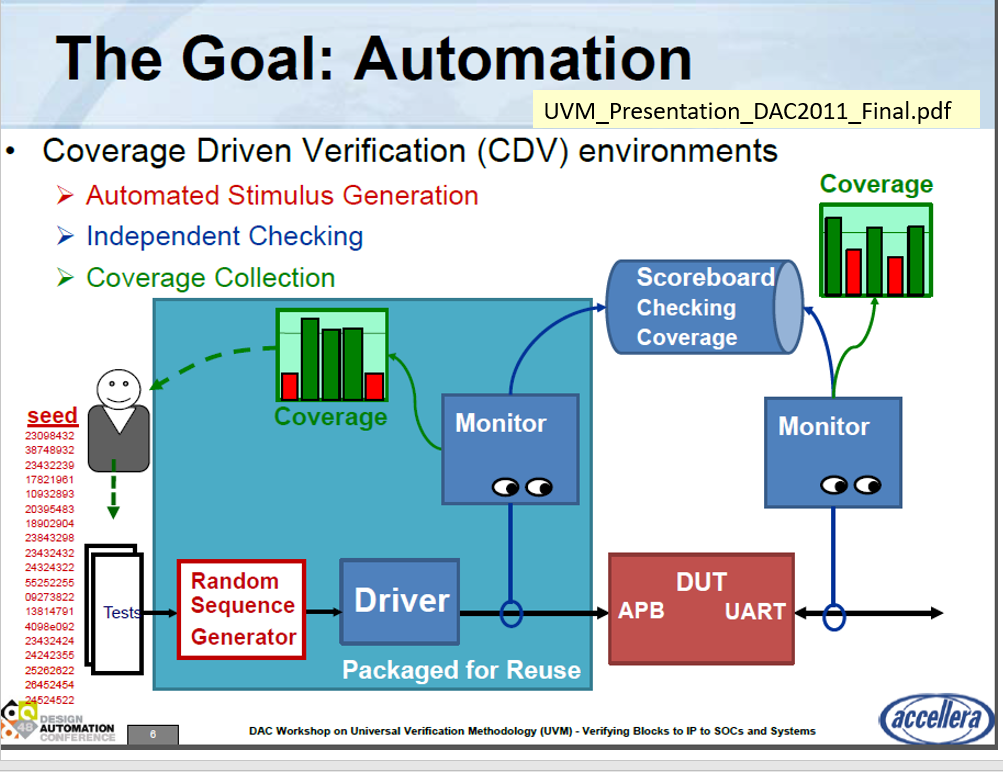
I was trying to create each components when my supervisor told me that things got way complicated than he expected so he basically provided me a verification plan which is this one:

!(file:///C:/Users/Trematerra/Downloads/889_786_1.png)

don’t know if you will be able to see it, but basically the Verification plan consists of: one Generator with one Transaction, two drivers (one for each side, write and read), at least 4/5 interfaces (one for write, one for read, one for the clock signals, one for the output flags and one for the internal signals such as pointers), two stimulus Monitor (always one for each side, write and read), one DUT Monitor shared by the two sides, a reference MODEL and a Scoreboard. Kinda tricky as TB architecture.

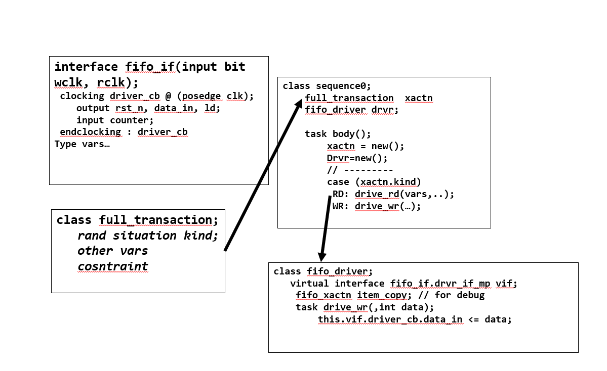
Anyway, until now I have came up with this code:
Transaction code:

class full_transaction;
    typedef enum {RD, WR, RD_WR} situation;
    
    rand situation cases;
    rand bit rinc;
    rand bit winc;
    rand bit [7:0] wdata;
    
    bit wfull;
    bit rempty;
    bit [7:0] rdata;
    
    constraint read_only {cases == RD -> rinc==1; winc==0;}
    constraint write_only {cases == WR -> rinc==0; winc==1;}
    constraint both_operation {cases == RD_WR -> rinc==1; winc==1;}
    //constraint write_full {}
    
    
    function void print_all();
        $display("rinc=");
    endfunction
    
endclass


Generator code:

class full_generator;
    //typedef enum {RD, WR, RD_WR, RD_EMPTY, WR_FULL} situation;
    
    int num_transactions = 200;
    full_transaction trans;
    mailbox gen2wdriv;
    mailbox gen2rdriv;
    
   
    event gen_done;
    //situation cases;
    
    function new (mailbox gen2wdriv, event gen_done, mailbox gen2rdriv);
        this.gen2wdriv = gen2wdriv;
        this.gen2rdriv = gen2rdriv;
        this.gen_done = gen_done;
    endfunction
    
    
    task main();
        repeat (num_transactions) begin
            trans = new();
            if (!trans.randomize()) begin
                $fatal(0,"Gen:: write_trans randomization failed.");
            end
            
            gen2wdriv.put(trans);
            gen2rdriv.put(trans);
            
        end
        -> gen_done;
        
    endtask


            //if (!randomize.(cases) with {cases dist {RD:=2, WR:=2, RD_WR:=1, RD_EMPTY:=1, WR_FULL:=1};}) begin
                //$fatal(0,"Gen:: write_trans randomization failed.");
                
endclass

Interfaces code:


interface write_if();
    logic winc;
    logic [7:0] wdata;
    
endinterface

interface read_if();
    
    logic rinc;
    logic [7:0] rdata;
    
endinterface

interface clk_if (input wclk, input rclk);
    
    logic wrst_n;
    logic rrst_n;
    
endinterface

interface flag_if();
    
    logic wfull;
    logic rempty;
    
endinterface

Driver, going to post only the write side:

class write_driver;
    mailbox wgen2wdriv;
    full_transaction trans;
    virtual interface write_if w_vif;
    virtual interface clk_if c_vif;
    
    //constructor function
    function new (virtual interface write_if w_vif, mailbox wgen2wdriv, virtual interface clk_if c_vif);
        this.w_vif = w_vif;
        this.wgen2wdriv = wgen2wdriv;
        this.c_vif = c_vif;
    endfunction
    
   /* 
    task reset();
        $display("Reset every interface signal");
        wait (!c_vif.wrst_n);
        w_vif.winc <=1'b0;
        w_vif.wdata <=8'b0;
        @(posedge c_vif.wclk);
        wait (c_vif.wrst_n);
        $display("Reset phase is over");
    
    endtask */
    
    
    //task to drive the signals from the driver to the interface
    
    task drive();
        $display("This task is used to drive the signals from the transaction to the involved interface");
            @(posedge c_vif.wclk);
            wait(wgen2wdriv.num()!=0); 
            
            trans = new();
            wgen2wdriv.get(trans);
            w_vif.wdata <= trans.wdata;
            w_vif.winc <= trans.winc;
        
          /* if (trans.winc && !w_vif.wfull) begin
                $display ("The generator randomized winc equal to 1 so a new write operation can be passed");
                w_vif.winc <= trans.winc;
                w_vif.wdata<= trans.wdata;
            end else begin
                $display("Winc is equal to 0 so a write operation cannot be executed");
                w_vif.winc<=1'b0;
            end */
    endtask
    
    task write_full();
        $display("This task is created to check what happens when the FIFO is FULL and the write enable is 1");
        repeat(16) begin
            @(posedge c_vif.wclk);
            w_vif.winc<=1'b1;
            w_vif.wdata <=$urandom(1);
            
        end
        
    endtask
    
    task main();
        while(!c_vif.wrst_n) begin
            w_vif.winc <=1'b0;
            w_vif.wdata<='0;
            @(posedge c_vif.wclk);
        end
        
        forever begin
            fork
                begin
                    $display("Thread for the drive function");
                    drive();
                end
                
                begin
                    $display("Thread to check what happens when the FIFO is full");
                    write_full();
                end
                
            join_none
        end
    endtask


endclass

The idea was to generate a random transaction with some constraints to cover 3 different situations: RD, WR and RD/WR at the same time by using that typedef, while for the Write_FULL and the Read_EMPTY scenarios, since I know the depth of the FIFO, I have implemented the task Write_full which repeats itself 16 times so I know it will happen. Then in the task main I did fork/join_none with those two tasks. Hope it makes sense my plan…still thank you for your help

In reply to GiuseppeT:
You’re in the right direction. Some comments:

  1. Clocks and interface
    It is much more common to have the clock passes as an argument to the interface. It is very uncommon to have an interface just for the clock. Thus, do this instead:
interface write_if(input logic wclk);
logic winc;
logic [7:0] wdata;
endinterface
interface read_if(input logic rclk);
logic rinc;
logic [7:0] rdata;
endinterface
  1. class full_transaction;
    Looks ok. On situation, you may need to add an IDLE condition
    // typedef enum {RD, WR, RD_WR} situation;
  2. class full_generator; write_driver
    Looks OK. You have 2 mailboxes,and in main you put transactions. That is OK.
    However, in write_driver you declare another mailbox mailbox wgen2wdriv;, but I don’t see the connection between the mailbox in full_generator and the write_driver. Also, where is the call to the full_generator.main()?

I understand that it is partial code. You still need to add the scoreboard/monitor and verifier.
In my SVA book I wrote a model of a traffic light controller with East/West nd North/South lights for use in formal. My first attempt at the design was to have 2 separate control logic, one for each direction with the 2 controls talking to each other. I struggled making it work because I had issues wtht he synchronization between the two controls. I ended up with one master control directing the traffic between the 2 logic units (i.e., EW NS).
My point here is that I see the possibility of some difficulties in having 2 separate, non-coordinated transactions and monitor without good coordination. After all, if you want to do a write on full or read on empty, there’s got to be coordination in creating the full or empty conditions before exercising the test.
I would prefore ONE interface, ONE triver with separate tasks (1 for rd, 1 for wr), constrained randomization to create the end conditions.

In reply to ben@SystemVerilog.us:

First of all, again, thank you for guiding me through this entire FIFO process. It is much appreciated because you are helping me more than expected so I am really grateful, just want you to know that.

Just want to update you about the fact that my supervisor told me that an asynchronous FIFO might be more complicated than expected so he decided to a first cut of the TB by imagining that is SYNCHRONOUS. So basically the two clocks are equal right now or at least that’s how I am proceeding.

The code is still same I guess, one transaction provided to the generator which randomize the entire transaction feeding two drivers, one for each side.

  1. I agree with you about having the clocks passed as arguments to the interface, that’s basically what I planned to do at the beginning but unfortunately my supervisor made a Verification plan where, as I told you before, I have like 5 interfaces: Write_if, Read_if, Clock_if, OutputFlag_if and Internal_if (this last one should provide the WR_pointer and the RD_pointer to the DUT monitor)

  2. I followed your advice and I have added an IDLE condition where I put winc=0 and rinc=0 when the variable situation (cases) happens to be equal to IDLE

  3. In the write_driver class I am declaring the same mailbox basically (you made me notice the names were not matching) to get the transaction coming from the full_generator; like in the full_generator class I am putting the transaction, while in the write_driver class I am collecting it to pass the signals to the interfaces. (there should be a get operation). The call for the full_generator.main I thought it was not needed but maybe I can create a task that goes:
    task drive ();
    forever begin
    main();
    end
    endtask

  4. Since my supervisor told me to use two stimulus monitor to feed the Reference Model (I believe they are the ones that drives the winc, wdata and rinc to the reference Model) and one Results_monitor (it should be the DUT Monitor that provides the output to the Scoreboard), this is the code I came up with:

//Write_stimulus monitor that provides the inputs from the write_side (winc and wdata)
class write_stimulus_monitor;
    mailbox wmon2mod;
    //mailbox wmon2scb;
    full_transaction trans_mod;
    //write_transaction trans_scb;
    virtual interface write_if w_vif;
    virtual interface clk_if c_vif;
    
    function new (mailbox wmon2mod, virtual interface clk_if c_vif, virtual interface write_if w_vif);
        this.wmon2mod = wmon2mod;
        //this.wmon2scb = wmon2scb;
        this.w_vif = w_vif;
        this.c_vif = c_vif;
    endfunction
    
    
    task main ();
        forever begin
            @(posedge c_vif.wclk);
            trans_mod = new ();
            //trans_scb = new ();
            $display("By using mailboxes, the signals coming from the interfaces need to go to the monitors");
            trans_mod.winc <= w_vif.winc;
            trans_mod.wdata <= w_vif.wdata;
            //$display("\t winc = %b, \twdata = %b", trans_mod.winc, trans_mod.wdata);
            
            //trans_scb.wfull <=w_vif.wfull;
            
            //$display("\t wfull = %b", trans_scb.wfull);
            
            wmon2mod.put(trans_mod);
            //wmon2scb.put(trans_scb);
        end
    endtask
endclass

//Stimulus monitor for the Read_side that provides the input to the Reference Model
class read_stimulus_monitor;
    mailbox rmon2mod;
    //mailbox rmon2scb;
    virtual interface read_if r_vif;
    virtual interface clk_if c_vif;
    full_transaction trans_mod;
    //read_transaction trans_scb;
    
    function new (mailbox rmon2mod, virtual interface clk_if c_vif, virtual interface read_if r_vif);
        this.rmon2mod = rmon2mod;
        //this.rmon2scb = rmon2scb;
        this.r_vif = r_vif;
        this.c_vif = c_vif;
    endfunction
    
    
    task main();
        forever begin
            @(posedge c_vif.rclk);
            trans_mod = new();
            //trans_scb = new();
            $display("let's pass the input signal from the interface to the monitor");
            trans_mod.rinc = r_vif.rinc;
            $display("\t rinc = %b", trans_mod.rinc);
            //$display("Let's pass the outputs to the Scoreboard");
            //trans_scb.rdata = r_vif.rdata;
            //trans_scb.rempty = r_vif.rempty;
            //$display("\t rdata = %b, rempty =%b", trans_scb.rdata, trans_scb.rempty);
            
            rmon2mod.put(trans_mod);
            //rmon2scb.put(trans_scb);
        
        
        end
    endtask
endclass

//Results monitor that get the outputs (flags and rdata) from the DUT through all the interfaces 
class results_monitor;
    
    virtual interface clk_if c_vif;
    virtual interface flag_if f_vif;
    virtual interface write_if w_vif;
    virtual interface read_if r_vif;
    virtual interface internal_if i_vif; //not sure if I need this 'cause it contains the pointers which I am not sure if I need to use them
    mailbox resmon2scb;
    full_transaction trans_scb;
    
    
    function new (virtual interface read_if r_vif, virtual interface write_if w_vif, virtual interface flag_if f_vif,
        virtual interface internal_if i_vif, virtual interface clk_if c_vif, mailbox resmon2scb);
        this.r_vif = r_vif;
        this.w_vif = w_vif;
        this.f_vif = f_vif;
        this.i_vif = i_vif;
        this.c_vif = c_vif;
        this.resmon2scb = resmon2scb;
        
    endfunction
    
    
    task main();
        forever begin
            @(posedge c_vif.wclk);
            trans_scb = new ();
            $display("This task is used to pass the DUT outputs to the results monitor");
            trans_scb.rempty <= f_vif.rempty;
            trans_scb.wfull <= f_vif.wfull;
            trans_scb.rdata <= r_vif.rdata;
            
            resmon2scb.put(trans_scb);
        end
        
    endtask


endclass


  1. for the reference Model (is it your verifier? I think so but not sure though) I am using a queue because it seems to me the obvious thing to use in SV to replicate the FIFO behaviour
    and this is the code I came up with:
class model #(parameter DSIZE =8, parameter ASIZE =4);
    
    
    mailbox wmon2mod; //These two mailboxes are used to pass the transaction from the Stimulus monitor to the Model
    mailbox rmon2mod; //So since it's about the stimulus monitors I am providing the winc, wdata and the rinc signals 
    
    mailbox mod2scb;//These two monitors are used to pass the outputs to the Scoreboard and then to the Coverage Collector
    mailbox mod2cov;
    
    full_transaction w_trans;
    full_transaction r_trans;
    
    localparam DEPTH = 1<<ASIZE; //Declaring the Depth of the FIFO by shifting 1 of four places
    
    bit [DSIZE-1:0] fifo_queue[$:DEPTH-1]; //If it is declared right, this is a queue of 8 bit with a maximum dimension equal to 16
    
    //Constructor Function
    function new (mailbox wmon2mod, mailbox rmon2mod, mailbox mod2scb, mailbox mod2cov);
        this.wmon2mod = wmon2mod;
        this.rmon2mod = rmon2mod;
        this.mod2scb = mod2scb;
        this.mod2cov = mod2cov;
        
    endfunction
    
    task create_outputs();
        wait(wmon2mod.num()!=0 && rmon2mod.num()!=0); //If the mailboxes containing the transactions that need to be passed
        //to the Model are empty, I am not allowed to go ahead.
         
        w_trans = new ();
        r_trans = new ();
        wmon2mod.get(w_trans);
        rmon2mod.get(r_trans);
        $display("Begin Model Operations");
       
       //Write operation on the FIFO
        if (w_trans.winc)begin //if the write_enable is equal to 1 begin the operation
            
            if (fifo_queue.size == 16) begin //if the FIFO is full, raise the wfull flag
                w_trans.wfull =1'b1;
            end else begin
                fifo_queue.push_back(w_trans.wdata); //if it's not FULL, then it is possible to write on the FIFO
            end
        end
        
        if (r_trans.rinc) begin
            
            if (fifo_queue.size == 0) begin
                r_trans.rempty =1'b1;
            end else begin
                r_trans.rdata <= fifo_queue.pop_front();
            end
        end


       /* if (w_trans.winc && !w_trans.wfull) begin
            fifo_queue.push_back(w_trans.wdata);
        end else if (r_trans.rinc) begin
            r_trans.rdata =fifo_queue.pop_front();
        end */
        
    endtask
    
    
    task main ();
        forever begin
            create_outputs();
        end
    endtask
    
    
endclass

I have some doubts about the Model because it’s getting two transactions from two different stimulus_monitors and for this reason I am using inputs from the two transactions, (you can see how in the If I have used w_trans.winc and r_trans.rinc). But point is, I am not sure if this is okay 'cause I should probably feed then the two transactions to the Scoreboard with outputs updated as well.

I am sorry because now that I look at this, it can be really confusing, normally I would just follow a damn standard Verification Plan for the FIFO but my supervisor is really confusing me sometimes

In reply to GiuseppeT:
Comments, blunt as they may be…

  1. Async vs Sync FIFO
    my supervisor told me that an asynchronous FIFO might be more complicated than expected so he decided to a first cut of the TB by imagining that is SYNCHRONOUS. So basically the two clocks are equal right now or at least that’s how I am proceeding.
    I disagree, the clocks don’t make that much difference.
  2. Multiple interfaces
    I have like 5 interfaces: Write_if, Read_if, Clock_if, OutputFlag_if and Internal_if (this last one should provide the WR_pointer and the RD_pointer to the DUT monitor)
    Too complex. Adding interfaces does not make it easier. An interface is a container. The code can use what it needs from one container.
  3. The verification approach
    It seems that you want a uvm-like approach without the UVM. I believe your “supervisor” is your teacher or thesis advisor. He is misdirecting you into the correct approach.
    If the gaol is UVM, you’re not doing that. This particular model can be verified with one simple module and some tasks. By that I mean the randomization or directed selection of the transaction to dermine the ‘kind’ of transaction to execute, and calls to wr task and rd task to drive the fifo that is instanced directly into the test module.
    This chart is a high-level uvm concept.
  4. This is a good vase for assertions in the interface and/or as a bind to the RTL.

You need to draw your approach before you build it. The model shows the interactions between the classes. I took an attempt at the mode to give you an idea as to what I meant.

best wishes to your success.
Ben